Circuit board
Jump to navigation
Jump to search

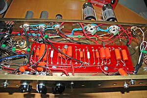

Circuit boards in the time before Integrated circuits, relied on separate electrical and mechanical connection between components.


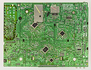
The bottom of a circuit board. The hundreds of spots of solder mark where components are attached, on the other side. Note the metal traces. The board has more layers of traces sandwiched together, allowing electrical connections to pass over other connections.
A circuit board holds electrical components firmly together, and provides an electrical connection between those parts.
In the days before Integrated circuits the board would just be a board, possibly with holes piercing it, to allow wires to pass through. The vacuum tubes, resistors and capacitors on the board would get their connection to the appropriate other components via a rat's nest of individual wires.
Modern circuit boards, sometimes called "printed circuit boards" are manufactured in a sandwich of layers, with electrical paths bonded to each layer.